Soca
Start of topic | Skip to actions
Provenance discussion, Chicago, May 2006
- Dates: 2006 May 8-10th
- Attendants: Simon Miles, Steve Munroe, Mike Wilde, Yong Zhao
Provenance Challenge
Brain Atlas Workflow
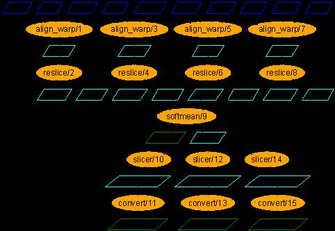
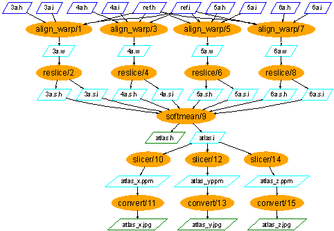
The case study workflow comes from the fMRI application and is a process for creating population-based atlases from the fMRI Data Center's archive of high resolution anatomical MR data, using a multi-stage I/O intensive pipeline that warps the anatomical features of the brain of multiple subjects into a standard space. The workflow is shown here. It is comprised of procedures, shown as orange ovals, and data items flowing between them, shown as trapeziums. It can be seen as five stages, where each stage is depicted as a horizontal row of the same procedure in the figure. The procedures employ the AIR (automated image registration) suite to create an averaged brain from a collection of high resolution anatomical data. In addition to the data items shown in the figure, there are other inputs to procedures (constant string options): we will make these evident in the workflow in the future. The inputs to a workflow are a set of new brain images (3.a to 5.a) and a single reference brain image (6.a). All input images are 3D scans of a brain of varying resolutions, so that different features are evident. For each image, there is the actual image (.i) and the header/metadata information for that image (.h). The stages of the workflow do as follows.- For each new brain image, it is compared to the reference image to determine how the new image should be warped, i.e. the position and shape of the image adjusted, to match the reference brain. The output of each procedure in the stage is a warp parameter set defining the warp to be done.
- For each warp parameter set, the actual transformation is done by creating a new version of the original new brain image with the configuration defined in the warp parameter set. The output is a warped image.
- All the warped images are averaged into one single image.
- For each dimension (x, y and z), the averaged image is sliced to give a 2D atlas along a plane in that dimension, taken through the centre of the 3D image. The output is an atlas data set.
- For each atlas data set, it is converted into a graphical atlas image.
Provenance Queries
We discussed (with regard to prospective provenance, for example), which provenance queries should be in scope for our discussions and for the Provenance Challenge. We distinguished, for one provenance query and one system:- Whether the query is within scope of the system
- Whether the query can be answered by the system
- Find the process that led to a graphical atlas image / everything that caused the graphical atlas image to be as it is. This should tell us the new brain images from which the averaged atlas was generated, the warping performed etc.
- Find all calls to procedure alignwarp, and their runtimes, with argument model=rigid that ran in less than 30 minutes on non-ia64 processors. The argument is given as a string option to the alignwarp procedure.
- Find the average runtime of all alignwarp calls with argument model=rigid that ran in less than 30 minutes.
- Find all procedure calls within runs of the workflow named /prod/2005/0305/prep, a version of the brain atlas workflow given above, whose inputs were linearly aligned with model=affine
- Find all output averaged images of softmean (average) procedures, where the warped images taken as input were align-warped with model=affine (i.e., where softmean was preceded in the workflow, directly or indirectly, by an alignwarp procedure with argument model=affine)
- Find all outputs of softmean that were resliced with intensify=3
- Find the outputs that were linearly aligned with model=affine and with input LFN metadata center=UChicago
- Find all the graphical atlas sets that have metadata annotation studyModality with values speech, visual or audio, and return all the annotation tags of this set of data
- Find all the metadata tags study on actual results of softmean that were linearly aligned with model= affine, and whose outputs have annotation state = IL
Future Actions
- Write-up Provenance Challenge call
- Provide concrete input, output and intermediate data files
- Each of Southampton and Chicago to attempt the Challenge
- Judge whether the Challenge is adequate for others to attempt
Integration of VDS and PASOA
VDS Concepts
For clarity of discussion, we agreed on the set of terms currently used in VDS, these being used in the VDC schema: A procedure is an executable application, e.g. /bin/date. An invocation is the act of executing (initiating, running, completing) a procedure. Each invocation has actual arguments passed to the procedure. A call is a plan to perform an invocation. The actual arguments bind to the formal arguments that are part of the definition of the procedure's interface. Most parts of the model can be annotated with typed annotations.Integration of PASOA into the VDS execution environment
In order to integrate PASOA into VDS, we need to provide greater functionality without adding limitations on existing functionality. Crucially, this means that queries that are currently performed over all the data in the VDC, not all of which PASOA considers to be process documentation or provenance, should still be executable (and with adequate performance). One solution is to have a single interface through which queries over all data currently held in the VDC can be performed, and that this interface is implemented by calls to navigation interfaces representing different types of data, e.g. process documentation, annotations, Grimoires service descriptions etc. This maps to the current state of affairs in VDS where a single SQL statement can query over multiple tables. For performance, this requires that the navigation interfaces used in joined queries are adequate to support those joined queries efficiently. An alternative solution is for a client to join the information from multiple sources, but this may have costs in performance and in implementing clients. To join over data, the implementation (whether a service or client) must be able to process all data together, which is hampered by the use of different data formats.P-structure Actors in VDS
We observed that a workflow running in VDS could be documented at different levels of granularity, and the flow would be expressed differently with each. We could document DAGMan calling each of the workflow activities in turn; we could separately document the execution of locating data (using RLS), data transfer and procedure execution; or we could just document the data flow as if one procedure was sending data directly to the next. There was a discussion about whether the coarse granularity process was valid within the semantics of the p-structure: we concluded it was by the following reasoning. An interaction p-assertion may document data flow (data being exchanged between actors), control flow (one actor initiating action by another actor) and/or causal flow (one actor receiving data because another sent it). In fact, it must always document causal flow to be used in provenance. Also, the semantics of high quality process documentation require that an interaction p-assertion always documents data flow (even if the documentation style removes the actual data). However, it does not have to document control flow: the sender may not intentionally or directly initiate action by the receiver. It must be clear, from the content of the interaction p-assertion, what types of flow it documents (e.g. a SOAP message documents all three). We distinguish different physical components involved in the execution of a workflow (DAX) in the Virtual Data System. These may or may not correspond to actors in the p-structure, depending on the modelling chosen. For these components we determine what they can record. What each can record is determined by what it has access to during execution: what it receives as input, reads from elsewhere or creates to be output.- VDC
- Pretty much everything else that components below know
- GenDAX?
- VDL
- Workflow DAG
- Planner (Euryale or Pegasus)
- Workflow DAG (DAX)
- Condor DAG
- Condor submit files
- Grid sites
- DAGMan
- Condor DAG
- Condor submit files
- Condor-G
- Condor submit file for each job
- RSL translation of Condor submit file for each job
- GRAM
- RSL translation of Condor submit file for each job
- Scheduler for Local Cluster
- Scheduler-specific translation of Condor submit file for each job
- Kickstart
- Application name
- Arguments
- Start and end times of application execution
- Local environment variables for execution
- GridFTP?
- Source file
- Destination file
- RLS Client (in context of procedure execution)
- Logical filename used in job
- Mapping of logical filenames to physical filenames
- Physical filename used in job
- RLS Server
- Mapping of logical filenames to physical filenames
- Each Application Executable
- Application name
- Arguments
- Start and end times of application execution
- Local environment variables for execution
- Executable-specific state information
P-Structure Model 1: Physical Components as Actors
In this model, each actor in the process documentation represents a different physical component in the system. This means that all the physical components defined above are modelled as a separate actor. As a slightly less fine-grained model, we may collapse particular sets of actors where distinction does not have much value, e.g. Condor-G, GRAM and Local Scheduler can be treated as a single actor (called Scheduler), RLS Client and Server treated as the same actor.Sharing Context
In order for Kickstart, GridFTP?, RLS Client and each application executable to know what interaction key to use in recording documentation about its interaction with the scheduler, this information must be given to it by the scheduler. In order for the scheduler to record its interaction with DAGMan, DAGMan must give it the interaction key.P-Structure Model 2: Nodes as Actors
In this model, all processes caused by one derivation and executed on a single node in a single workflow run is represented by an actor. These node actors each include Kickstart, GridFTP?, RLS Client and the application. Additionally, we would still model the enactment of the workflow with an actor representing DAGMan, which would interact directly node actors (i.e. Condor-G, GRAM and Local Scheduler are ignored).Sharing Context
As in the above model, actors need to share interaction keys, but in this case there is a single interaction key passed by DAGMan to all the components running on a node.P-Structure Model 3: Dataflow Activities as Actors
In this model, every actor corresponds to a node in the DAX and includes the components: a logical component within DAGMan representing an workflow activity, Kickstart, GridFTP?, RLS Client and the application. Interaction between these actors corresponds to data flowing between procedures in the workflow. This model corresponds most closely to that currently recorded in the VDC.Sharing Context
For each file output from one actor and received by another, DAGMan will create an interaction key. As a component of every actor, DAGMan uses this key for its sender and receiver assertions for the interaction. It also passes the key to the other physical components of an actor (Kickstart, application executable etc.) so that they can record other p-assertions about that interaction, as in the model above.Services and Applications
We discussed the differences caused by a workflow containing services vs. one containing application executables. As a service is just a component taking input and producing output and this is also true of application executables, there is no practical difference between such workflows. All the above models could apply to a service workflow as much as an application workflow. However, a service-oriented approach implies certain assumptions and patterns which are not the same as those used by VDS, which takes application executables as the most likely forms of procedure.Composite vs Black-Box Procedures
In VDS, there are composite procedures, but these do not correspond to physical applications, they map to a sub-workflow of atomic procedures. In PASOA's service-oriented approach, we assume that any procedure (service) may call other procedures directly and that this is part of the process that can be exposed in the provenance. In both systems, we can make a composite procedure (i.e. a procedure that calls other procedures) provenance-aware, so that both it and the procedures it calls record process documentation. In PASOA, this is achieved by wrapping all procedures so that they record p-assertions. In VDS, it is achieved by breaking up the logic the composite procedure so that it uses the VDS approach to exchange data with the other procedures as defined by derivations.Input/Output vs Job Submits
In a service-oriented approach, it is expected that a response from a service contains data which is a function of the data in the request to the service. In VDS, input and output logical filenames are provided on executing a procedure, and nothing is returned in response. The procedure interacts with the local filesystem (and RLS depending on which model used) to get the actual input data stored previously and to record the output data at the end of the procedure. In recording p-assertions about VDS processes, we may not document the exact command-lines, but instead use a documentation style which makes it appear that input data is given on request and output data returned on response. This makes it easier to assert relationships between inputs and outputs.Mapping Process Documentation
We (manually) mapped the process documentation as stored in VDC to the same data expressed in the p-structure, using the actors described in Model 3 (P-structure Actors in VDS section) above for a small, two-stage workflow. We model a simple two stage workflow: prog1 -> prog2.- prog1 takes in a string and produces a file output.txt
- prog2 takes in the file output.txt and produces output.gif
- Invocation table:
- inv1:
- start_time = ...
- duration = ...
- site_id = ...
- call_id = ipaw::prog1_call
- procedure_id = ipaw::prog1
- arguments = "hello world" output.txt
- inv2:
- start_time = ...
- duration = ...
- site_id = ...
- call_id = ipaw::prog2_call
- procedure_id = ipaw::prog2
- arguments = output.txt output.gif
- inv1:
- Procedure table:
- ipaw::prog1 (in string arg1, out lfn arg2)
- ipaw::prog2 (in lfn arg1, out lfn arg2)
- Call table:
- ipaw::prog1_call (arg1="hello world", arg2 = output.txt)
- ipaw::prog2_call (arg1=output.txt, arg2 = output.gif)
- There are three interactions:
- ipaw::prog1 makes an interaction p-assertion about I1, containing the "hello world" input string
- ipaw::prog1 makes an interaction p-assertion about I2, containing the output.txt output logical filename
- ipaw::prog2 makes an interaction p-assertion about I2, containing the output.txt input logical filename
- ipaw::prog2 makes an interaction p-assertion about I3, containing the output.gif output logical filename
- The procedure definition (was transformation definition) of ipaw::prog1 is an actor state p-assertion for I1
- The procedure definition of ipaw::prog2 is an actor state p-assertion for I2
- A relationship p-assertion links output.txt in I2 to "hello world" in I1
- A relationship p-assertion links output.gif in I3 to output.txt in I2
- The relationship p-assertions also provide the connection between the actual arguments and the formal argument names by declaring the latter as parameter names in the p-assertion
- The invocation record (output by kickstart) for ipaw::prog1 is an actor state p-assertion about I2
- The invocation record (output by kickstart) for ipaw::prog2 is an actor state p-assertion about I3
XDTM and PASOA Queries
In PASOA's provenance store, there are currently two query interfaces: a provenance query interface for graph traversal and an XQuery interface. The XQuery interface is implemented using a mapping of database contents to an XML DOM structure, so that XQueries can be executed over the DOM. The mapping code is generic and re-usable, but the concrete mapping to the p-structure is manually created. XDTM requires similar mappings, but with automatic creation of the mapping. Yong and Simon agreed to work together on moving the mapping technology into XDTM and automating it for generic XML Schemas. The provenance query interface needs to traverse a graph of process documentation, where different p-assertions may be in different languages. For practicality in querying, the interface requires that mappings are provided from non-XML data to XML formats. This would ideally use a technology such as XDTM. Therefore, XDTM will be integrated into the provenance query interface.Future Actions
- Split the VDC contents and doing a manual join of data outside the database, to see the practical consequences
- Design an interface to the provenance store specifically for navigating and extracting the exact information required by VDS
- Develop the provenance store's DOM mapping technology into XDTM
- Integrate XDTM into the provenance query interface
to top
| I | Attachment  | Action | Size | Date | Who | Comment |
|---|---|---|---|---|---|---|
| | ipaw_wf1.dax | manage | 15.2 K | 08 May 2006 - 21:55 | SimonMiles | Case study workflow DAX |
| | ipaw_wf1.vdlx | manage | 21.7 K | 08 May 2006 - 21:55 | SimonMiles | Case study workflow VDLX |
| | ipaw_wf1.vdl | manage | 6.8 K | 08 May 2006 - 21:57 | SimonMiles | Case study workflow VDL |
| | simple_pstructure.xml | manage | 11.5 K | 08 May 2006 - 22:04 | SimonMiles | P-structure documetation for simple workflow |
| | ipaw_wf1.pdf | manage | 23.2 K | 09 May 2006 - 14:21 | SimonMiles | Case study workflow graphic |
| | Workflow2.jpg | manage | 30.7 K | 09 May 2006 - 22:54 | SimonMiles | Brain Atlas Workflow |
| | BrainAtlas.png | manage | 5.1 K | 09 May 2006 - 22:57 | SimonMiles | Brain Atlas Workflow |
Edit | Attach image or document | Printable version | Raw text | More topic actions
Revisions: | r1.6 | > | r1.5 | > | r1.4 | Total page history | Backlinks
Revisions: | r1.6 | > | r1.5 | > | r1.4 | Total page history | Backlinks